# Challenge modeling switch S3 in 4-Port DC-DC Converter on RT Box 1 (Sub-cycle Averaging issue)
**URL:** https://forum.plexim.com/t/challenge-modeling-switch-s3-in-4-port-dc-dc-converter-on-rt-box-1-sub-cycle-averaging-issue/2740
**Category:** RT Box
**Tags:** plecs-coder, rt-box, c2000
**Created:** [December 5, 2025, 8:55pm UTC](https://forum.plexim.com/t/challenge-modeling-switch-s3-in-4-port-dc-dc-converter-on-rt-box-1-sub-cycle-averaging-issue/2740 "2025-12-05T20:55:11Z")
**Posts on this page:** 4
**Page:** 1
### Author:  [@FredericoSaviano](https://forum.plexim.com/u/FredericoSaviano)
#### Post date: [December 5, 2025, 8:55pm UTC](https://forum.plexim.com/t/challenge-modeling-switch-s3-in-4-port-dc-dc-converter-on-rt-box-1-sub-cycle-averaging-issue/2740/1 "2025-12-05T20:55:11Z")
Hello everyone,
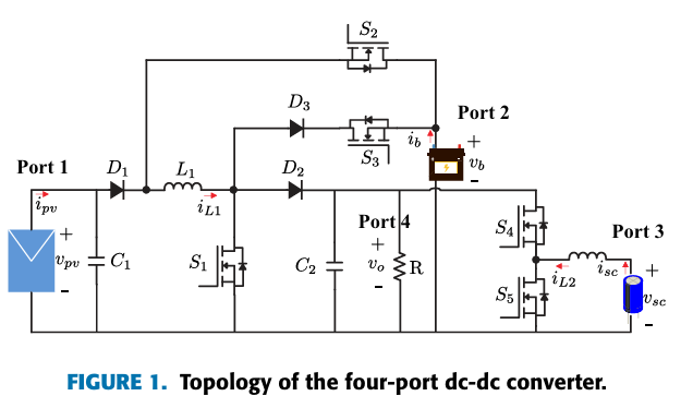
I am currently working on a HIL simulation of a 4-port DC-DC converter topology (shown in the attached images) using the **PLECS RT Box 1** controlled by an external DSP. The system operates with a switching frequency (fsw) of 50kHz.
**Current Setup:**
- **Hardware:** RT Box 1 + External Microcontroller.
- **Time Step:** I am achieving a simulation step size of 2us.
- **Inputs:** Gate signals are read via the **PWM Capture** blocks.
The Success:
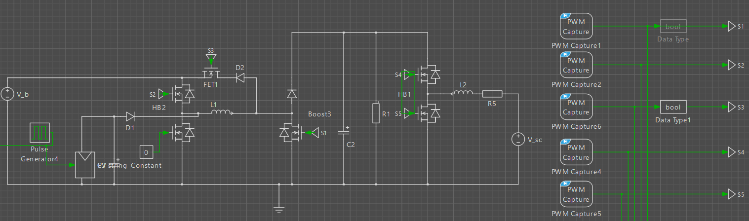
For switches S\_1, S\_2, S\_4, and S\_5, I successfully implemented the Sub-Cycle Average (Hybrid) mode by using the standard “Half-Bridge” and “Boost” power modules from the PLECS component library. This allows me to utilize the high-resolution duty cycle information (float output) from the PWM Capture blocks, maintaining simulation accuracy despite the discrete time step.
The Problem:
I am facing a significant issue modeling switch S\_3 (referring to the topology diagram). Due to the specific connection of this switch (in series with a diode connecting the inductor node to the battery), I cannot map it to a standard Half-Bridge or Boost module without encountering algebraic loop errors or unsupported DC source connections within the block logic.
Current Workaround & Failure:
As a temporary solution, I am modeling S\_3 using a discrete MOSFET primitive. However, this forces me to convert the high-resolution “PWM Capture” signal (float) into a Boolean signal.
Since my time step is 2us and the period is 20us (50kHz), I only have 10 sample points per cycle. This coarse resolution is causing significant jitter and inaccuracies in the simulation. Consequently, the control loops involving S\_3 are failing to stabilize or transition states correctly.
My Question:
Is there a recommended method to implement Sub-Cycle Averaging for a standalone switch like S\_3 that doesn’t fit the standard power modules? Or is there a way to configure a generic power module to accept this specific topology without triggering connectivity/loop errors?
Any insights or modeling suggestions would be greatly appreciated.
Thank you!
---
### Author:  [@Bryan\_Lieblick](https://forum.plexim.com/u/Bryan_Lieblick)
#### Post date: [December 9, 2025, 4:11pm UTC](https://forum.plexim.com/t/challenge-modeling-switch-s3-in-4-port-dc-dc-converter-on-rt-box-1-sub-cycle-averaging-issue/2740/2 "2025-12-09T16:11:21Z")
> Is there a recommended method to implement Sub-Cycle Averaging for a standalone switch like S\_3 that doesn’t fit the standard power modules?
One cannot develop a sub-cycle average model for a standalone switch. The sub-cycle average models must be derived at the converter level and require certain port characteristics (e.g. for a half-bridge one side must be connected to a positively biased capacitor or DC source and the output terminal connected to an inductor).
> Or is there a way to configure a generic power module to accept this specific topology without triggering connectivity/loop errors?
Implementing the model with standalone switches will have poor performance as you have identified, since the state of a standalone switch can only be determined once per model step. One could use time-scaling to achieve more simulation steps per switch event, but the model does not run in true real-time.
In short this topology is not supported by the RT Box for real-time simulation.
---
### Author:  [@FredericoSaviano](https://forum.plexim.com/u/FredericoSaviano)
#### Post date: [December 9, 2025, 5:42pm UTC](https://forum.plexim.com/t/challenge-modeling-switch-s3-in-4-port-dc-dc-converter-on-rt-box-1-sub-cycle-averaging-issue/2740/3 "2025-12-09T17:42:17Z")
Thank you for the clarification regarding the standalone switch limitations.
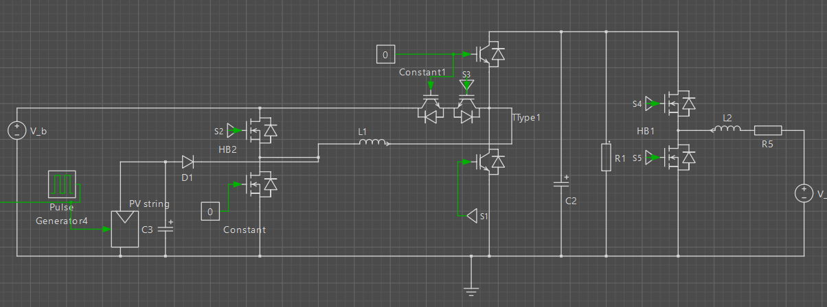
Since my last post, I attempted a workaround by mapping the topology to a **3-Level T-Type Power Module** (as shown in the attached screenshot). Physically, the connections appear to fit the structure of the converter I am modeling.
However, I encountered a constraint with the module’s internal logic. It seems the T-Type block enforces specific commutation rules (likely designed for standard inverter operation/interlocks). Specifically, I observed that the module forces a dependency between the switches: the converter only operates as expected if the logic state of the middle switch (my S\_3) is consistent with the main leg (S\_1). If I attempt to drive them into states that contradict standard T-Type commutation (e.g., trying to keep S\_3 open while S\_1 is in a specific state), the module overrides my signals or behaves incorrectly, effectively forcing S\_3 to follow S\_1.
Is there a known method to bypass or disable this internal commutation logic/interlock within the standard Power Modules? Or is there a way to configure a generic power module structure that allows for this specific connection (creating a custom sub-cycle averaged block) without inheriting these pre-defined state constraints?
Any further advice on how to ‘break’ this logic link would be very helpful.
---
### Author:  [@Bryan\_Lieblick](https://forum.plexim.com/u/Bryan_Lieblick)
#### Post date: [December 10, 2025, 4:23pm UTC](https://forum.plexim.com/t/challenge-modeling-switch-s3-in-4-port-dc-dc-converter-on-rt-box-1-sub-cycle-averaging-issue/2740/4 "2025-12-10T16:23:23Z")
It would be helpful if you could post a model for further analysis including one that shows the expected operation in the switching mode and unexpected operation in sub-cycle average mode.