After I replaced the IGBT with Gan, the output voltage is not five-level. The signal I gave to the IGBT before was a pulse of 0 and 1. I want to know what caused the output level to be wrong. Is it because the GaN is not conducting normally? How can I solve this problem?
CHB_GaN.plecs (200.1 KB)
GS66516.xml (11.2 KB)
IKQ75N120CS6_igbt.xml (7.0 KB)
IKQ75N120CS6_diode.xml (5.6 KB)

You have the GaN Rds_on set to 25 ohms rather than 0.025 ohms (it should be in milliohms). This is why the full Vdc bus voltage is not reflected in the output voltage waveform.
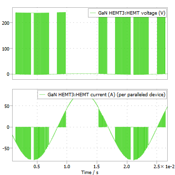
I followed your step, the output voltage is correct. But using the GaN , its loss is greater than the IGBT loss. I uploaded the figure (GaN current and voltage). I think is negative current problem. But I am not sure.
To be clear, this is more a modeling problem and device selection issue than a PLECS issue. Be aware that the GaN device sees peak currents approaching 80A, although it’s a 60A rated device. That may not be super problematic, but you can expect higher losses. Also, with the IGBT and reverse diode, the diode conducts the reverse currents, whereas with the GaN device, the additional diodes serve no purpose. I’m not exactly sure what you are trying to do, but to simply compare the losses from two different technologies is not straightforward without considering the circuit conditions.