I am trying to design a 5 and 6 phase motor using the 3 phase motor (VBR model) in the Component Library as a template. I have done simulation with the 3 phase model and am trying to extend the simulation to a higher number of phases. I am using this model instead of the rotor reference frame model because of what is said in PLECS documentation about interfacing that model with external diode circuits.
However, I am having trouble completely understanding how the variable inductance is computed in the model.
When I looked under the Lss block mask, I did not understand what was going on with the block named “Mdq → Muvw”. That block has a number of combinations from the output of the Mab block adding. The eventual output “Lss_uvw” going to the variable inductance seems to have 18 outputs (9 from the “Mdq → Muvw” block and 9 zeros). It is not intuitive to me what is going on there. PLECS documentation describes the model, but does not go into as much detail with the computation of the inductances in that block.
I’d like to know what purpose the “Mdq → Muvw” block serves. I’m also open to recommendations for using the rotor reference frame model if feasible.
Firstly, are you aware of the 6-phase machine model included in the TI C2000 Target Support Demos + Motor Drives + Six-phase PMSM? That model uses a rotor-reference frame based implementation (with snubbers).
Regarding your question, the Mdq->Muvw block is used in at least two machine models - the Non-Excited Synchronous Machine (Lookup) and the Open Winding PMSM. In both cases the block does essentially what the name suggests - converts the Lmidd, Lmidq, and Lmiqq incremental inductances into the abc domain. These inductances changes as a function of rotor posotion (and DQ currents in the case of the lookup model). The phases are also coupled, so the inductance matrix in the abc domain is 3x3 time-varying inductance matrix.
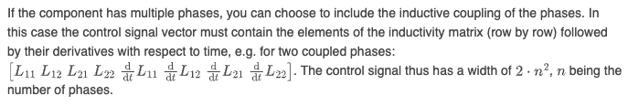
The Variable Inductance component is the component best-suited to model time-varying inductance matrix. If you review the help of the component you’ll note the following:
This explains the width of [9 9]. The machine model uses the incremental (and not absolute) inductances and so the set of dL/dt terms can all be zeros, as explained later in the Variable Inductor documentation.
Regarding the derivation of the actual equations - I have a jupyter notebook I can share with you showing the transformation. I’ll send that via a direct message.