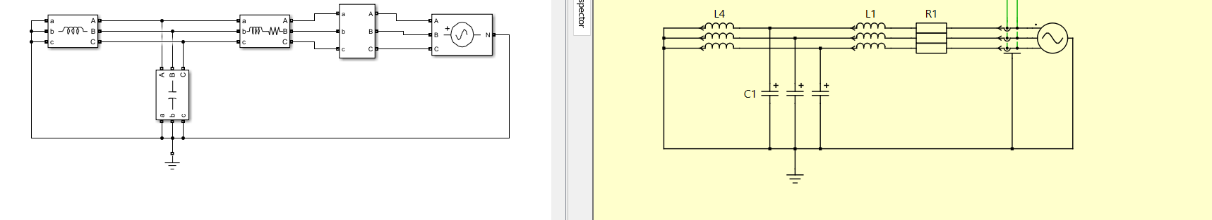
Hello, I would like to ask a question. I am building a 3-phase RLC circuit with a configuration as shown in the attached image. I am modeling the circuit in both Simulink and PLECS. Both models use the same parameters for R, L, and C values. I have also set the initial current values for each inductor according to the theory for RLC circuits. However, I set the initial voltage of the capacitor to zero. The current measurement results show a difference between PLECS and Simulink, but this difference only appears in Phase A. For Phases B and C, the results still appear different. If you have any suggestions, which parameter should I consider adjusting in the PLECS model?
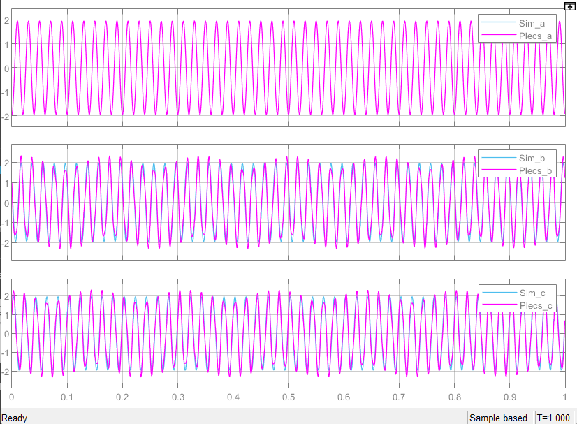
Results:
Here I attached also the program initialization:
%% Parameter initialitation
Ri = 0.01;
Labc = 3e-3;
Labc_1 = 9e-3;
Vpp_rms = 10;
freq_in = 50;
Cabc = 1e-3;
Vln_peak = Vpp_rmssqrt(2/3);
omega = 2pi*freq_in;
%% Calculate initial current for impendance and capacitance
% Total Reactance paralel XL & XC
Lc_paralel = 1/((1/(omegaLabc))+(-omegaCabc));
% Phase angle for Z = R + JX
phase_angle1 = atan(((Labc_1*omega)+Lc_paralel)/Ri);
% Magnitude Impedance Z = R +JX
Z_im = sqrt(Ri^2 + ((Labc_1*omega) + Lc_paralel)^2);
% Magnitude for Reactance paralel XL & XC
Z_im2 = sqrt(Lc_paralel^2);
% Initial current L1
I_init3 = (Vln_peak/Z_im)sin([0 -2pi/3 2*pi/3]-phase_angle1);
% Initial current L4
Vz_im2 = (Vln_peak/Z_im) * Z_im2; % Voltage in paralel branch
I_init4 = Vz_im2/(Labcomega)sin([0 -2pi/3 2pi/3]-pi/2); % Initial current
% Initial Voltage C1
V_init = [0 0 0];
It appears that the datapoints that are included for each solver step are accurate, but that they are linearly connected in the Scopes, producing a “non-smooth” output and missing of the min/max of the sinusoids in some areas. If that’s the case then having additional points rendered would help, however you don’t need to simply reduce the tolerance or step size settings in order to achieve this.
Please instead try increasing the “Refine Factor” setting, which will insert additional points to the waveform rendering using already calculated higher-order polynomial details from the integration routine. This setting can be found in the main tab of the PLECS Standalone preferences window and the Model Configuration Pane: Data Import/Export for Simulink if you are using PLECS Blockset.
Increasing from the default of 1 to a value of 5, would be a reasonable starting point to try.
Thank you for your suggestion Kris, I think i should give you the more detail differences for additional information. This current measurement in plecs still showing the different value when i modelled the same parameters with simulink. I expected that Inductor and capacitor in plecs need to define the initial value both for initial current for (L) and initial voltage for (C). But, there still a difference on phase B and C, Is it really increasing “refine factor” would be the solution or maybe there are another setting parameters that i need to fix?
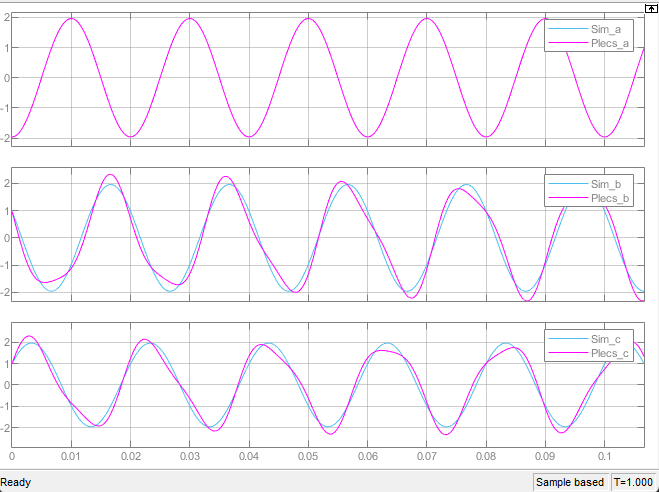
Thanks for providing a “zoomed in” view. Indeed the Refine Factor helped smoothen the waveforms, but you are right there remains a discrepancy. In your other recent post my colleague pointed you to the starting initial conditions that are required in PLECS to match what Simulink is expecting- did you try this?
Are you using the same Simulink solver settings between the two models?
It was already solved by finding the correct value for Initial Voltage for capacitor. Finding value of Initial voltage could be decided by considering the voltage value in Capacitor branch. But must be remembered that in Capacitor having a characteristic that The current is leading from voltage. In contrast the Inductor having a characteristic that The current is left behind from the voltage. So the phase shift on Initial voltage in capacitor would be zero. Finally, this problem solved by deciding the Initial voltage in capacitor correctly. Thank you for your help in advance