Hello, Currently I have designed the simulation of grid forming inverter in Plecs blockset that is integrated with Simulink. I use Simulink to provide control signal to Plecs blockset as a grid plant. In another hand, I also have a grid forming inverter with controller but all is modelled in simulink. All between two models both in PLECS and SIMULINK is having the same parameter, however after i run the simulation, the result of the measurement in voltage and current is remain different between (plecs + simulink) model and all in one simulink model. So my question, Is there any limitation when i am using plecs + simulink so it gives different result? or is it must be the same result if I set all the parameters correctly? Is there any suggestion?
One could reasonably expect the results to be quite similar if the model aligns between the two tools. Is there a gross error or a small error?
Often times the issue is that the PLECS and Simulink models differ or have different parameters (i.e. there is a user translation error). More subtle reasons would be that library blocks can behave slightly differently between the two tools possible for example how our modeling approach interacts with the solver.
For suggestions, I would recommend a systematic debugging approach breaking down your model into smaller pieces and validating if each sub-component behaves different across the two tools. In same cases you may also be able to port over the model bit-by-bit. I don’t have a Simscape license and cannot assist you with the debugging process.
Error in my models related with the transient respon, when i run between this two models actually different in transient respon.
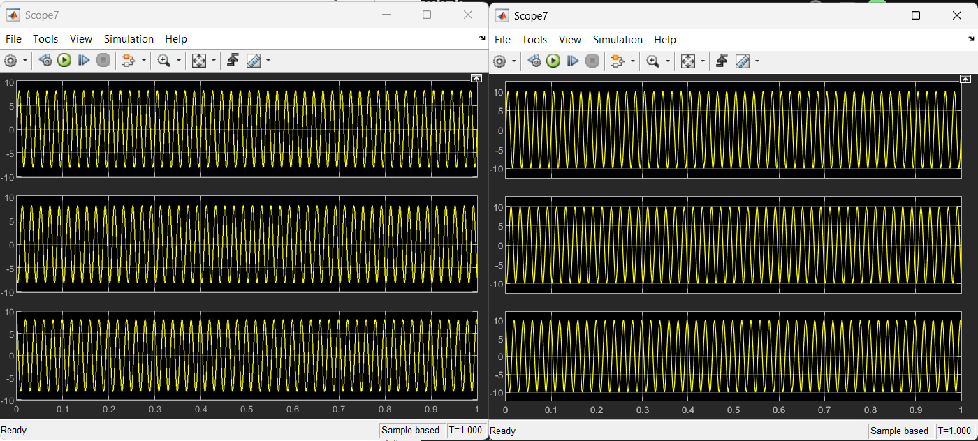
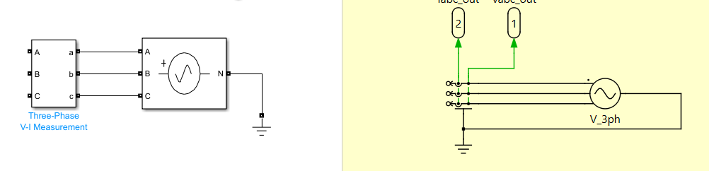
Thank you for your suggestion, I have already try to breakdown the models into small part and try to test every block between simulink and plecs. I have found that the Three phase programmable voltage source in simulink and Voltage source ac 3 phase in plecs having a different result measurement voltage. With the same parameter setting (V = 10; frequency = 50 Hz; Phase = 0), the models give the different result. Is there any difference between block Three phase programmable voltage source in simulink and Voltage source ac 3 phase in plecs? Here I attached the result between simulink and plecs blockset. For the left plot is SIMULINK model and Right plot is PLECS models.
Sorry, This is the true model. I revise the model i attached before with removing the inductor components it is still remain the same result with amplitude of abc voltage in simulink and plecs still remain different
The Amplitude parameter of the “Voltage Source AC (3 Phase)” component in the PLECS library is the peak line-to-neutral voltage. Looking at the documentation for the “Voltage Source (Three-Phase)” Simulink component the voltage is the RMS phase-to-phase voltage. The two parameters are different. You can easily convert:
V_rms_ll * sqrt(2/3) = V_pk_ln
This aligns with your graphs. I assume you have a voltage of 10, so the line-to-neutral peak value is 10V in PLECS and 8.165 in Simulink.
Thank you for your help and detail explanation ![]() Now my Voltage measurement showing the equal value between these two simulation. I need to ask you again. I add the inductors into this 3 phase circuits then i measure the current value. It is showing also a different value in PLECS model. This result is actually equal but It is showing down shifting sinusoidal current than the simulink models. Is there any theoritical clue that you can show to me related with this issue? Thank you in advance
Now my Voltage measurement showing the equal value between these two simulation. I need to ask you again. I add the inductors into this 3 phase circuits then i measure the current value. It is showing also a different value in PLECS model. This result is actually equal but It is showing down shifting sinusoidal current than the simulink models. Is there any theoritical clue that you can show to me related with this issue? Thank you in advance
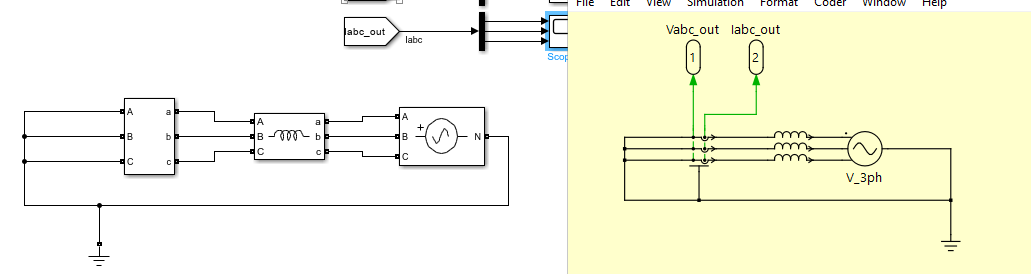
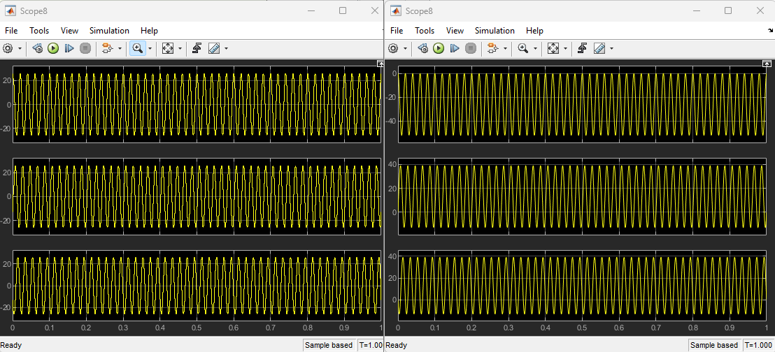
The Simulink model appears to assume that the currents are starting at a balanced initial condition and determines the required initial current. In PLECS, it is assumed the initial current is 0 (unless otherwise specified). Since you have no resistive damping in your circuit, this will appear as an offset in the PLECS current measurements.
You can calculate the initial currents for your PLECS model
I_init = V_pk_ln/(2*pi*F*L)*sin([0,-2*pi/3,2*pi/3]-pi/2) and then assign the currents to each phase inductance as I_init(1), I_init(2), and I_init(3).
Thank you for your explanation, You were expedient ![]()
One last question, so if i want to add some components like capacitor and resistor either parallel or series configuration there will be some adjustment in calculation for initial current in Inductor and initial voltage in capacitor?
If you want a “flat-start” type of behavior where the is no transient, then you need to set the initial conditions for the states. You can also run the simulation to a point where the initial transient settles out, but you will need some resistive damping in your circuit.
You can also store the conditions from a previous run and set as the initial conditions from your next run - for example find the electrical conditions at steady-state and then apply various faults from the same initial condition.
Hello Bryan, Is it possible in PLECS if I calculate the I_init with the L value but in complex number? So, I initiate the XL value with the imaginary part to be JXL? is the initial current and initial voltage need to provide the complex number to have an exact value for initial current and initial voltage?
Yes you can use complex numbers in calculations, but you must a) convert them to real numbers when used in the PLECS model (i.e. real/imaginary or magnitude/angle) and b) clear them from the Octave workspace in PLECS Standalone. See: Obtain PLECS parameter initial values from a .m file - #6 by Bryan_Lieblick