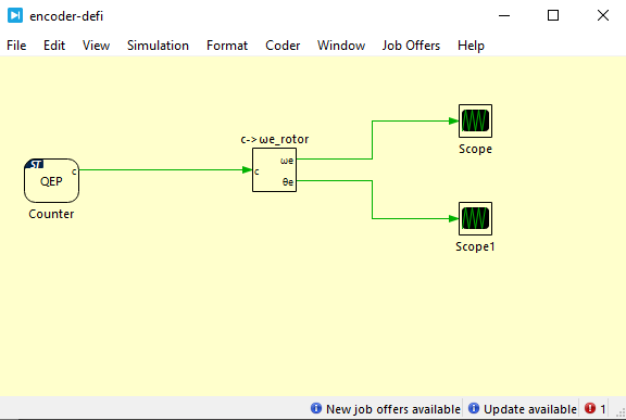
I am currently using the circuit below to read the position and speed of an encoder via the STM, using a scope. However, the signals I’m receiving fluctuate drastically between values, with no intermediate readings.
Hello Ranieri
May I ask you to post a .plecs file and a picture of the results that you are seeing to help me reproduce your results?
Also note that an update to the STM32 TSP was released this week (STM32 TSP 1.5.1). I would recommend updating to the new version!
Hello Ranieri,
Thank you for sharing your model and your scope results!
I modified your file to include a QEP signal generator to facilitate testing to isolate the issue.
I also applied some additional changes to the model:
- I switched from a fixed step solver to a variable step solver (this is recommended for the vast majority of simulations).
- I defined a discretization step size in the initialization commands. I also used the same discretization step size for the sample time parameter in the subsystem that computes the angle and the angular velocity from the counter value.
- I increased the number of samples used to compute the angular velocity.
- The “Maximum counter value” in the QEP block and the “Number of pulses per mechanical revolution” now both depend on n_encoder, defined in the initialization commands.
- I placed the model in a subsystem enabled for code generation. This allows us to model and simulate electrical connections between input and output pins.
- General note: A good practice to keep interdependent parameters in sync is to define them using variables, which are defined either in the initialization commands or a subsystem mask. An example of the latter is the subsystem created for the position and speed computation, which can be viewed by right-clicking on the subsystem and then selecting Subsystem→Edit mask….
After implementing these changes, I obtain the expected results, both in simulation and on the target. Note however that the subsystem used for the position and speed calculation is not robust to direction changes (this should affect only the offline model) and large changes to the angular velocity, the measurement of which is sensitive to the number of samples used for the speed calculation.
encoder-defi-edited.plecs (121.1 KB)


Thank you for attaching the PLECS scope images!
My QEP counter jumps between two values if I disconnect one phase (although I then observe a symmetrical waveform), so my starting point for analysis would be to double-check every pin connection. A tricky aspect of this specific model is for example that pin B7 (the phase A QEP input) is on CN7 whereas the other three pins are on CN10. If you are looking for an alternative to ST’s documentation, you can download the Launchpad-Nucleo Interface documentation from the Plexim website to identify pin connections on your Nucleo board: https://plexim.com/download/documentation .
If all pin connections are verified, I would try to look at the signals coming from your DC motor using an oscilloscope. Depending on the source of your QEP signal, you may also need to change the input characteristic from pull-up to pull-down.
Finally: I assume that your QEP counter waveform is a scaled version of your theta waveform. May I ask you to verify that?
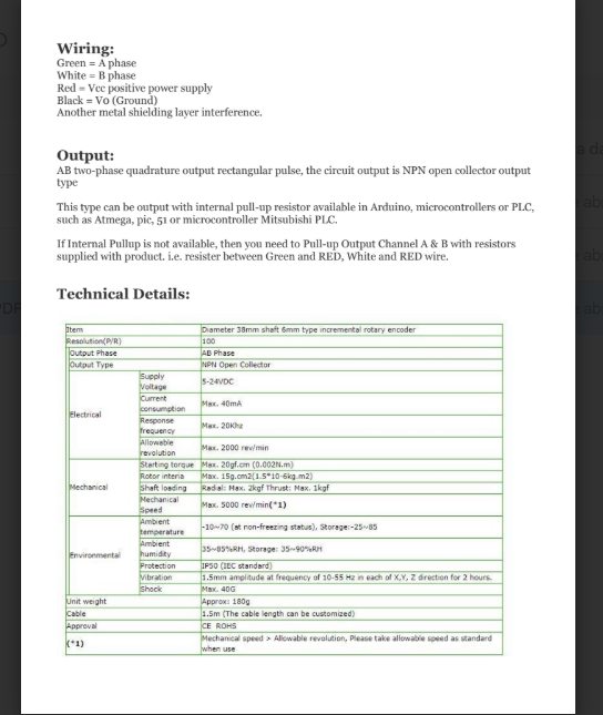
On the encoder, I have phase A connected to pin B7 and phase B to pin B6. The red wire is connected to the STM’s 5V supply, and both the ground and the metallic shield are grounded to the STM as well. Next, I will provide the QEP output.
I tried verifying the input doors and the output from the encoder using one of the outputs alone, for some reason one of tha phases is reading nothing at all (I tested both on the same input B7). The encoder is sending Voltage whe I spin in both so i dont think that he is the problem, to be fair idk
If one of the phases is not being read, that would explain the observed waveforms.
How did you try to read the two phases individually (i.e. did you use a Digital In block or an Analog In (Triggered) block or adopt a different approach)? Did you try different input characteristics (pull-up, pull-down, high impedance)?
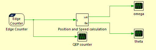
I am using the same logic as the ‘QEP’ block, but instead I replaced it with an edge counter and tested phases A and B. However, phase A is not being read, even though I can measure it with a multimeter when rotating the encoder.
I am able to read pulses using the Edge Counter block on both B7 and B6.
If you successfully read phase B on pin B7, but reading phase A on pin B7 did not work, I can only think of two reasons why this might be the case:
-
Phase A requires a different input characteristic than phase B (e.g. pull-down instead of pull-up).
-
The phase A signal coming from the encoder does not have the electrical characteristics that we expect (e.g. the electrical signal may not be varying between GND and +3.3 V).
If neither of these causes apply, I think debugging this would require a web meeting where we can see your board and your motor. If you are interested in setting up a web meeting, please email support@plexim.com.
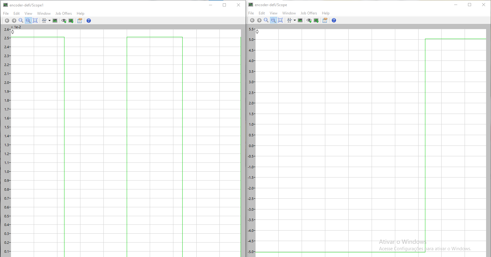
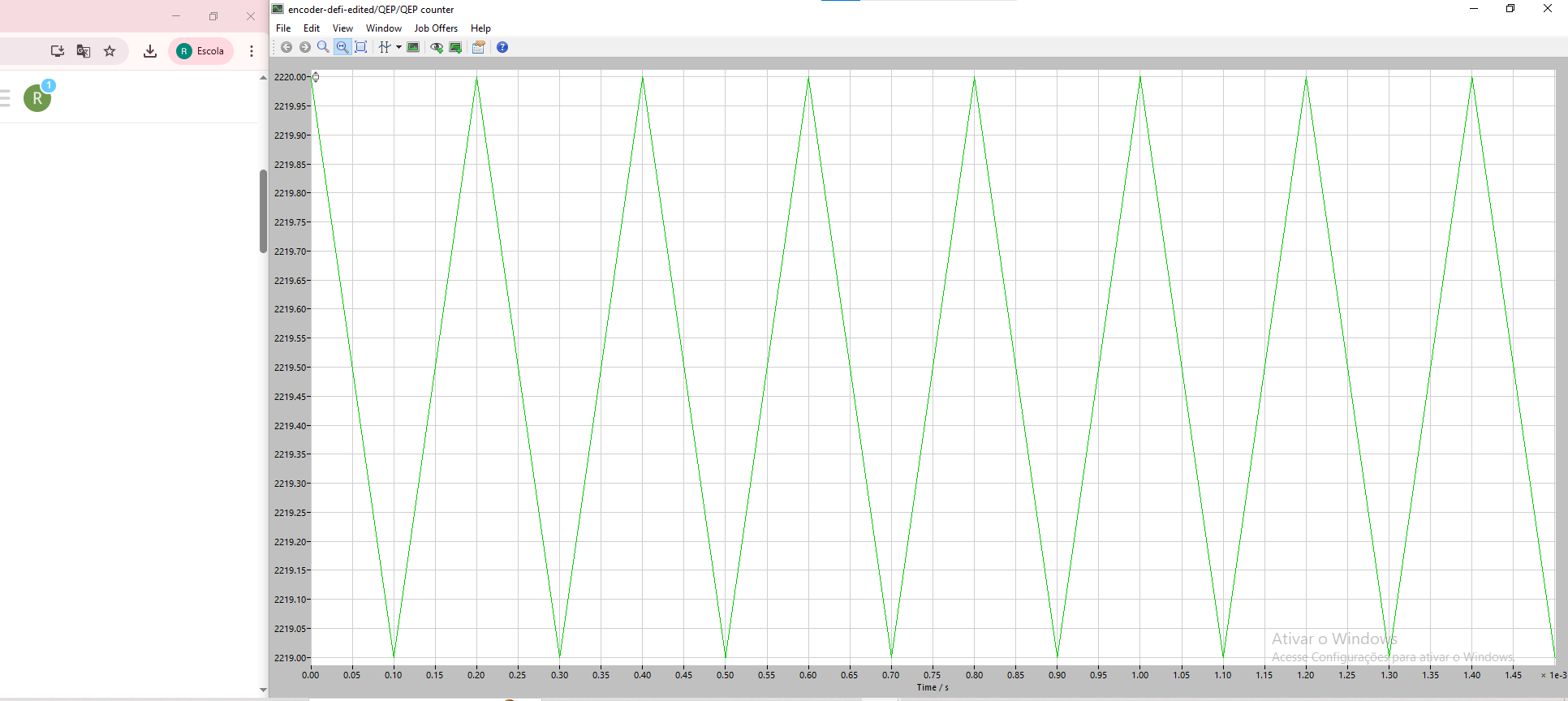
My QEP block outputs are toggling between 1 and 0 as expected. However, the omega and theta outputs are problematic. The theta output only varies between 0 and 6.2×10^-3. The Omega output shows no variation; regardless of the encoder speed, the value remains constant at 0.6 and then drops to 0.
The c (“counter”) output of the QEP block should not be toggling between 1 and 0. It should increment or decrement at every step depending on the direction of rotation. Theta will be equal to the c output of the QEP block multiplied by a scaling factor. If the QEP output is toggling between 0 and 1, it makes sense that the theta output would be toggling between 0 and 6.2e-3. Omega will not be calculated correctly if theta just toggles between two values.
The QEP block connections are correct, and the configurations I am using are the same as the file you sent earlier. Is there any other way to measure speed and position, or do you have any additional tips on how to configure it?