Hi everyone,
I’m currently a master’s student researching thermal modeling for power semiconductors.
In my study, I’m focusing on how the thermal coupling effect increases the junction temperature. I’ve already modeled this effect in the thermal network using From and Goto blocks in PLECS, so the temperature increase due to coupling is properly reflected in the thermal circuit.
However, I would now like to reflect this increased junction temperature in the power loss calculation of the semiconductor device. As you know, in PLECS, both junction temperature and power loss are computed based on the thermal description. So I believe I need to feed back the updated temperature into the power loss model.
The problem is, I’m not sure how to achieve this in PLECS.
Could anyone guide me on how to include the thermal coupling effect when calculating power loss?
Any suggestions or examples would be greatly appreciated.
Thanks in advance!
Can you provide your model files or screenshots of how you are modeling the effect in your thermal network? If the network is directly interfaced to the semiconductors then the heating effects should be seen in the loss calculations as the device junction temperature(s) are used during each iteration in the thermal loss table lookups.
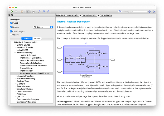
However, you might be interested in seeing the Thermal Package Description concept where you can enter the thermal impedance between individual semiconductor devices and the case of a package in a matrix format. Therefore you can implement not just the self heating but also the thermal coupling between each device. Please see the section I am referring to in our documentation in the attached image.

Thank you for your help.
In my model, the thermal coupling effect is implemented by extracting the power loss of the semiconductor device and using it as the input to the RC network of the Thermal Component.
In other words, the power loss calculated from the thermal description of the semiconductor is externally routed and applied to an RC thermal network, rather than being directly connected within the Thermal Description. Because of this, I was concerned that the temperature rise caused by thermal coupling might not be properly reflected in the power loss calculation.
Thermal Package Description seems to be unavailable because my license is an old version.
For your reference, I’ve attached a screenshot of my model.
In the picture, In2 represents the power loss of the T1 semiconductor
Please let me know if this approach might cause a discrepancy, or if you have any suggestions for improvement.

Thanks for confirming that indeed your thermal circuit is external and not directly interfaced. In this case, I do expect there to be a discrepancy.
Is the required coupling just for two switches, such as in a half-bridge arrangement? If so, have you considered just connecting a single thermal resistance in between the devices as follows?
At the moment, I’m considering the thermal coupling effect among 12 semiconductor devices.
I haven’t looked into the method you suggested yet, but it sounds interesting. Could you please explain it in more detail?
I believe a deeper understanding of the concept would help me assess whether it can be applied effectively in my case.
In addition, I’m planning to include a heatsink in the thermal model at a later stage, so the modeling approach I choose now needs to be compatible with that as well.
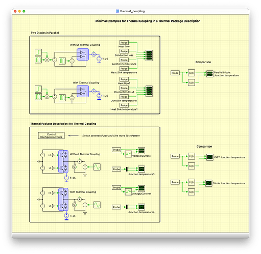
Please see the following from our documentation. We also include an example model for this topic in PLECS for you to explore yourself.
Thank you for the detailed information. I told you before that my licensed version is old, but when I checked it, it’s 4.5 version. The document in the picture now appears to be 4.9 version, but I think we need to upgrade the version for more accurate simulations. Before the version upgrade, I wanted to see if there was a way to do it without the upgrade, but I don’t think so. Thank you for your help.
The thermal package impedance concept where you can characterize the thermal coupling between individual semiconductors with an impedance matrix was introduced in PLECS version 4.8. But yes, regardless, you will need to upgrade from 4.5 to be able to use this feature.
As you advised, I’m going to upgrade the software within this week. Thank you for your help. Have a nice day.


