I am trying to simulate a simple circuit in which I include thermal models (based on datasheet plots) for the IGBTs, and am trying to compute conduction and switching losses. I keep a negative switching loss error that I have created as a warning and cropped. The switching losses are also incredibly high. The temperatures, though, seem reasonable
I have included my simulation file, thermal model, and link to datasheet for switches. Please advise on what can be done to fix it.
Simple_Circuit_with_error.plecs (84.0 KB)
IXYH50N120C3.xml (248.1 KB)
Link to Datasheet: https://mm.digikey.com/Volume0/opasdata/d220001/medias/docus/7082/DS100343CIXYH50N120C3.pdf?_gl=1*h6myo2*_up*MQ.._gsMQ..&gclid=CjwKCAjw7_DEBhAeEiwAWKiCC3CmqAAN6yVL7pAHw4ArTAzZNJ2n9a6HeOCFF9ynecrQW1jXejNyIRoC4aoQAvD_BwE&gclsrc=aw.ds&gbraid=0AAAAADrbLlgJLOLon4iZDSIISUc2UbdUI
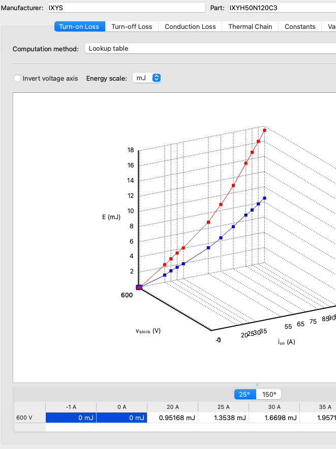
Unfortunately both the switching and conduction losses are extrapolated beyond zero into the negative loss regions, which is causing an incorrect thermal runaway condition. In the modified thermal description that I have attached, you will see that the losses are now “clamped” to zero and the simulation works as expected:
IXYH50N120C3.xml (288.7 KB)
Thank you very much, Kris.
I want to understand how the losses are extrapolated beyond zero by PLECS, and how the fix you implemented makes the difference between correct and incorrect operation. I haven’t seen that in PLECS documentation, but I stand to be corrected on that. I will be grateful for explanation or reference to relevant material on the matter.
Also, if I encounter a similar error in the future, but I have made sure to implement the thermal models as accurately as possible from the datasheet information, will you advise that I use a fix similar to what you did?
Your lowest switching loss values were at 20A before, and so for small currents the solver could linearly extrapolate past zero into the negative current region and calculate a negative loss. It’s similar for the conduction losses. By adding a point of 0J and 0V at 0A we ensure that these are not going into the negative region, and one more zero loss point beyond that (at -1A in my example) ensures the losses are truly “clamped” there so that extrapolation due to numerical “noise” wouldn’t allow small negative losses from being calculated. I think that small negative losses were adding up leading to an unstable simulation, but this has now been fixed.
In general, we advise that you have a loss value at 0A for both switching and conduction loss for this reason!
Hi Kris,
I modified the input to the circuit, and run into the negative switching loss errors I had before. I, therefore, extended the switching loss data in the thermal model to more negative currents to ensure that losses were clamped at zero, but I still see negative switching loss present, and the temperature of the switches involved becomes impractically high. In addition, there is an error report with not being able to meet integration tolerances without going below minimum allowable step size.
I have attached the thermal model and the PLECS file (again I have added the datasheet link), and would very much appreciate suggestions on how to make the simulation work well.
Simple_Circuit_with_error.plecs (175.1 KB)
IXYH50N120C3.xml (248.1 KB)
Datasheet: https://mm.digikey.com/Volume0/opasdata/d220001/medias/docus/7082/DS100343CIXYH50N120C3.pdf?_gl=1*h6myo2*_up*MQ.._gsMQ..&gclid=CjwKCAjw7_DEBhAeEiwAWKiCC3CmqAAN6yVL7pAHw4ArTAzZNJ2n9a6HeOCFF9ynecrQW1jXejNyIRoC4aoQAvD_BwE&gclsrc=aw.ds&gbraid=0AAAAADrbLlgJLOLon4iZDSIISUc2UbdUI
If you look at your currents and voltages you will see that you have a circuit implementation issue, not a thermal model problem. The temperatures go out of control because the switches see such high currents and voltages. I recommend you unassigned thermal descriptions first and get the electrical circuit operating properly and then re-enable the thermal models.