Hi all,
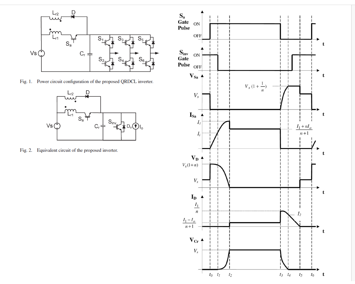
I’m reproducing the topology from “Three-Phase Soft-Switching Inverter With Minimum Components” in PLECS. I’m using a Linear Transformer to emulate the coupled inductor, plus the auxiliary switch Sa, clamp diode D, and resonant Cr.
What works / what I see
-
PWM/SPWM and gating run; Mode-1..3 look reasonable.
-
Vcr responds, and changing the diode forward drop affects how completely Cr discharges (higher Vf → deeper discharge, but I also get overshoot). Since, in the paper’s graph Vd starts with Vs (100V) and then gets to 0V so should I put 100V as Vf?
The blocker
-
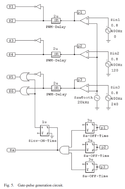
After the first cycle Sa turns ON and never turns back OFF. If I generate Sa with an AND of three monoflop pulses (one per phase edge), it stays high forever.
-
Switching the combiner to OR (so Sa = NOT(OR(pulses))) allows Sa to drop, but then I get a “state discontinuity after switching” in the inductors inside the Linear Transformer.
Tooling / control uncertainties
-
The paper uses a PWM Delay and flip-flops; in PLECS I substituted Blanking Time/Transport Delay and Edge Detection + Monoflop.
- I’m unsure about generating Q̅ cleanly and matching the paper’s timing exactly.
-
I loaded the Infineon thermal MOSFET models and set device deadtime = 0 (paper handles timing externally). I don’t see any change, should I worry?
What I’m asking
-
Best practice to combine the three Sa-OFF pulses (per phase edge)?
-
Common causes/fixes for state discontinuity when using Linear Transformer as the coupled inductor (wiring/polarity of the clamp, tiny parasitics, solver/event settings)?
-
Clean PLECS equivalents for the paper’s PWM Delay and SR flip-flops (especially Q/Q̅).
Setup / parameters
-
SPWM: 400 Hz sine refs (0.8 p.u., 120° shift), carrier 20 kHz (±1). Vs: 100 V
-
Load: L = 2.86 mH, R = 9.6 Ω.
-
Aux network: Lr = 17 µH, Cr = 10 nF.
-
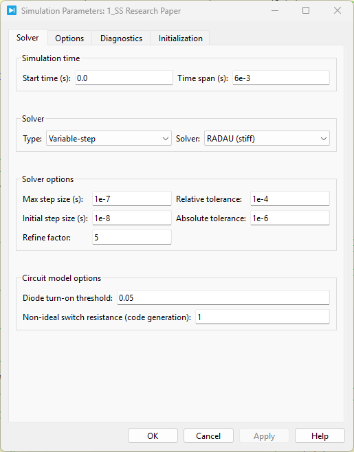
PLECS: Standalone; Linear Transformer in place of coupled inductor; Infineon MOSFET w/ diode models; device deadtime set to 0.
This is my first PLECS build, any wiring/logic pointers or minimal example snippets would be hugely appreciated. Thanks!

SS Research Paper.plecs (104.7 KB)