In the control system of a multiphase synchronous buck converter, the regulation is organized as a cascade: an outer voltage controller and an inner current controller. The voltage controller generates the desired current reference, and the current controller ensures that this current is achieved by producing the modulation index from the error between the measured and desired current.
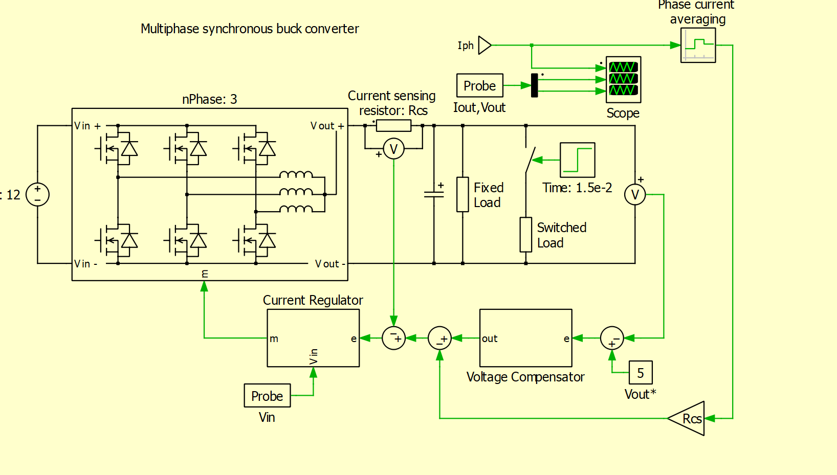
In the PLECS demo, the current reference * Rcs is first scaled with the shunt resistor and then subtracted from Iph*Rcs which gives an error. I would expect this to be the input for the current regulator. However, before this stage a second subtraction is performed with Vcs. Can somebody explain why this extra subtraction step is necessary?
There are a total of N instances of the PI Current Regulator, each used to regulate the inductor current of respective phase. Based on the number of phase (active) it needs to distribute the total load current (here Vcs) among all the phase. So the first subtraction is the total load current regulation feedback and the second subtraction is actually a vector of each phase inductor current feedback to balance this total load current among themselves. This is one of the simplest auto current balancing techniques. If your control is aware of the total active phase (N), then you can simply divide the load current by N to generate the current reference for each phase. But if you don’t know how many active phase are sharing the load then auto-balancing methods come into the picture.