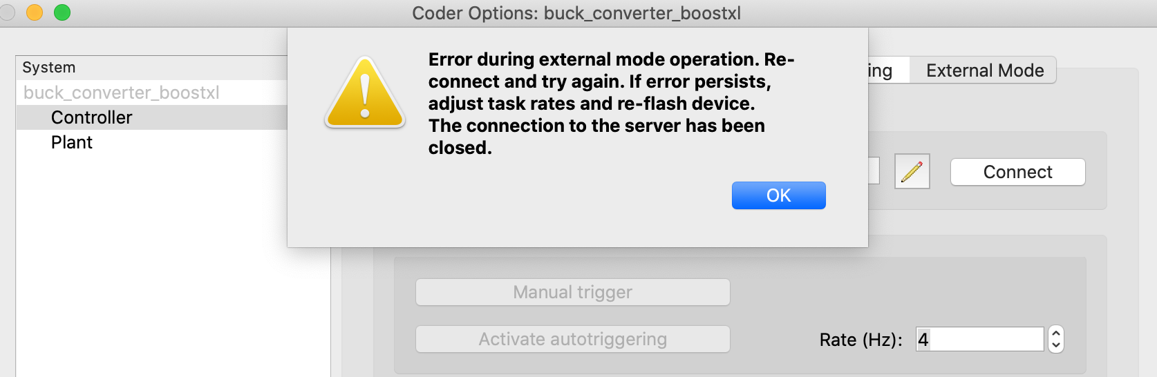
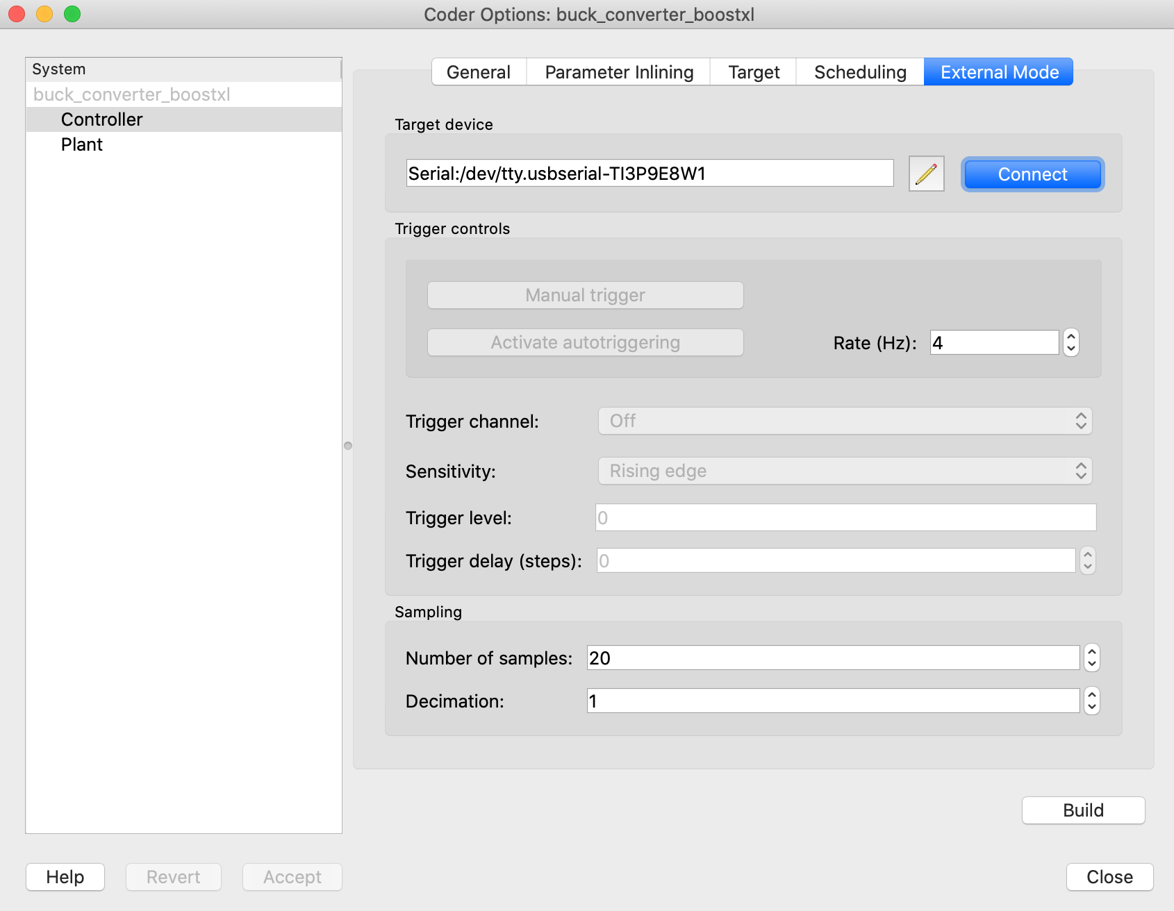
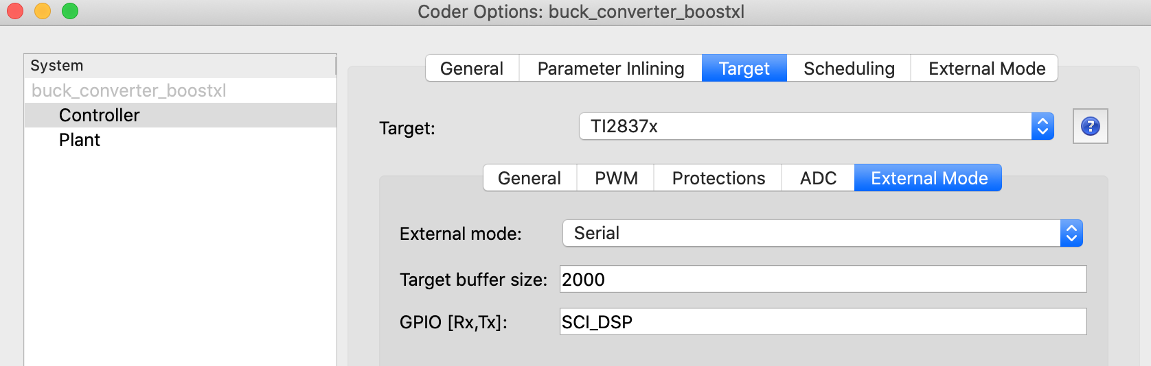
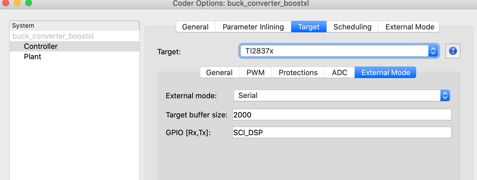
I want to run the system in external mode. I followed the instructions in your document above, and everything seems to work fine. Eventually, I use Activate Autotriggering, and the scope in the controller subsystem displays signals updating in real time.
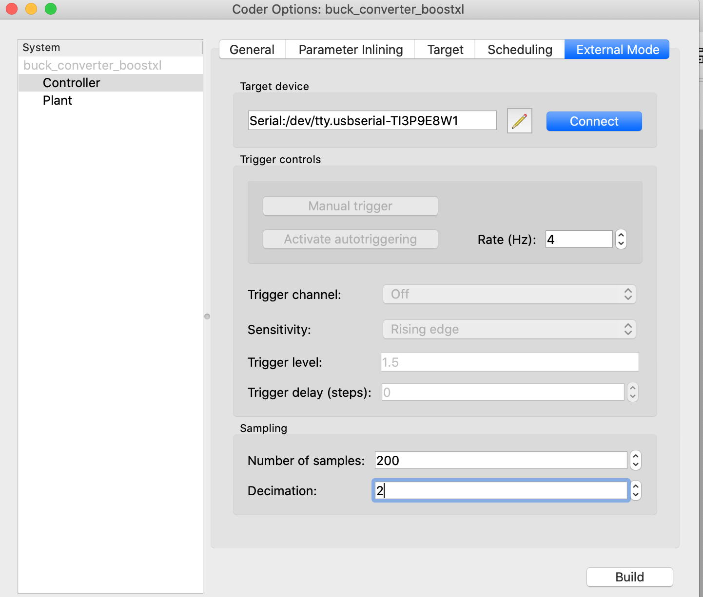
I click Connect, and Activate Autotriggering, it will connect fine again, the scope in the controller would show the signals in real time, but then PLECS gives me the same error posted above again after a few seconds (I set the Number of samples to 20 and decimation to 1, was 200 and 2, respectively, to try reduce the communication burden, but it did not help). I also tried to Build the project again from the external mode tab above, without improvement.
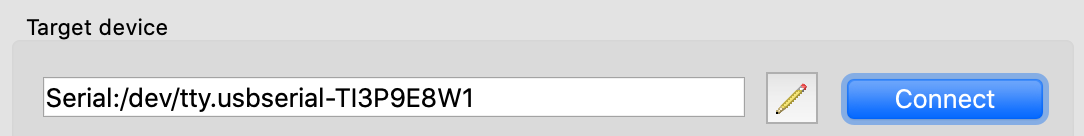
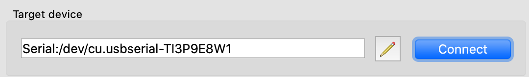
In the serial port in my MAC, I have tried to connect choosing either using “tty.usbserial“
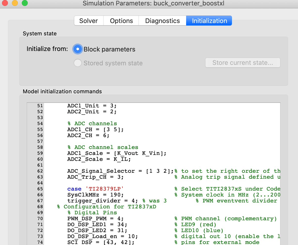
One thing you could try is to divide down the highest frequency task - this can be changed in the initialization parameter by adjusting the parameter “trigger_divider”. For the 28379 it is set to 3. Try with the trigger divider set to 4.
This will change your control task execution rate from ~66.66kHz to 50kHz and with that reduction you might get the additional time needed to service the overhead added by the external mode.
I changed line 67 in the below to 4 (was 3 as you said). Does this mean that while the converter switches at 200 kHz PWM (5 us), the control is run at 25 kHz (40 us)? i.e., an interrupt where the adc samples the measurement and the control is run occurs at every 40 us? Thanks again
Glad that helped - are you able to run your experiments without running into overrun issues? As for your question:
“I changed line 67 in the below to 4 (was 3 as you said). Does this mean that while the converter switches at 200 kHz PWM (5 us), the control is run at 25 kHz (40 us)? i.e., an interrupt where the adc samples the measurement and the control is run occurs at every 40 us? Thanks again“
That’s correct for this model because the ADC trigger is set to underflow. The PWM module is highly flexible and can be configured in several ways, which directly affects the trigger frequency. For example, if the ADC trigger is set to underflow and overflow with a task divider of 4, then at a 200 kHz switching frequency your control task will run at 100 kHz.
I recommend reviewing the documentation. Chapter 2 includes a section on control task triggering and explains the various configuration options available.
Additionally, the peripheral modules also provide an offline version that mimic what the HW will do when you flash it. I’ve created this simple offline model for you to play around with to see how the ADC trigger and ADC trigger divider interact with each other. Here is a set of experiments you can run:
simulate the model as is and save the trace
change the ADC trigger to underflow and overflow and keep the trigger divider the same. You’ll notice both the delay and resolution of the sampled ADC. save the trace again.
next keep the ADC trigger to underflow and overflow and change the trigger divider to 2 and you’ll notice that the sampled waveform is the same as the first simulation run.
Yes, with setting the ADC divider to 4 (rather than 3), the buck converter hardware keeps running in external mode smoothly, without freezing.
Thank you also for sending the link to the documentation. As per the example file “trigger_test.plecs“ that you attached, would it be possible for you to re-send it? Unfortunately when I open it it shows some error, and I am not sure what the problem is
If your project and license allows it I would recommend updating to PLECS 4.9 as there are bug fixes in place and you can also use the latest TSP which adds support for the F29H85 mcu.
Here are the release notes on what has changed in PLECS between 4.8 and 4.9: Release Notes | Plexim .
If you are curious about the target support package release history that can be found here towards the bottom of the page: TI C2000 Code Generation | Plexim