I am currently working on building my RT Box coder for implementing phase shift modulation in a three-phase dual active bridge design. As part of the process, I need to generate a phase delay of 60° between each signal. Despite trying various approaches within my knowledge, I have not been able to achieve the desired phase delay.
This issue is critical as I am unable to provide the necessary signals to my controller without resolving it. I would greatly appreciate your guidance in troubleshooting and resolving this problem. Your support in helping me figure this out at the earliest would be invaluable.
You have asked the same question in both the Plexim forum and through the support@plexim.com support channel. In the future please ask in only one location as it results in duplicate efforts from our engineering team.
In response to your support ticket where a model was included, my colleague suggested to use a PWM Out (Variable) block from the RT Box Target Support Library. The PWM Out (Variable) block can have a variable phase (and switching frequency) that is controlled by the block inputs. This approach allows PWM generation on the RT Box FPGA which has a significantly smaller clock resolution than is achievable when explicitly modeling carriers using blocks like the Triangular Wave Generator within the simulation.
You should be able to model most modulation schemes using this approach.
The problem for me is about the integer number When I try to build the RT box with my simulation with use PWM Out (Variable) but still have the same issues. I provide a constant value of 1/8 to get the required output the which will go to the triangular signals and used frequency is 65000 Now I’m facing the sampling time issues again. Can you guide me to fix it like how to fix the integer issues? Kindly help me to sort out this. with out figure out I can’t able to go forward.
which will go to the triangular signals
You should not directly generate the PWM carriers in the PLECS simulation model but rather use the PWM Out (Variable) block which includes an internal modulator.
Have you seen the “Three Phase Dual Active Bridge” minimal example demo, accessible in the RT Box Demo Models + Basic Topologies + Minimal Example? It shows how to generate the PWM signals for this converter. The model is attached for your convenience and shows the recommended approach to generate these signals with the PWM Out (Variable) block.
three_phase_dual_active_bridge.plecs (49.9 KB)
I attempted setting up the reference for my requirements, but encountered some errors. I have attached the details for your review. Kindly check and provide an update.
Your model is not prepared to run on the RT Box as you are using discrete switching devices rather than the appropriate components from the PLECS library. The error message is intended to prevent users from making this common modeling mistake.
I would recommend reviewing the RT Box: From Offline to Real-Time tutorial to better understand how to configure a model to run on the real-time simulator.
The “3-Phase Dual Active Bridge” component from the Electrical + Nanostep section of the PLECS library is the closest analog to your topology. Note the component does not include the magnetizing inductance or secondary capacitance. If the magnetizing inductance is sufficiently large then it could be neglected and the secondary capacitance could be reflected to the primary side.
Real-time thermal modeling is not supported with the Nanostep implementation of this model.
There are other, less optimal, ways to construct a real-time model for this converter but the real-time accuracy will likely be insufficient without using workarounds such as running the model in slower than real-time (i.e. time scaling).
Lastly, there also is the question of the overall simulation goals as this model has both the converter and controller modeled on one RT Box. Will you eventually interface this with a controller or hardware prototype?
Hello,
I’m trying control my duty cycle in my simulation using python. I need to check the phase shift in ON Stage so its possible though externally do you have any refence python script for it
I do not have a python script for that specific application but there are many general resources on using python with PLECS.
- There are demo model examples on using python including “Buck Converter with Parameter Sweep” for automating PLECS and the " XML/JSON-RPC Scripting Interface" demo model for the RT Box.
- Both the PLECS and the RT Box manual have chapters fully describing the python interface.
- See the “XML-RPC Interface and Controller Design in Python” tutorial for a more advanced example of scripting PLECS .
Hello,
Thanks for the support, currently the controller running fine but I have one more concern currently the controller have one deadtime for primary and secondary but I like to improve the converter by providing different deadtime for primary and secondary. Is it possible ???
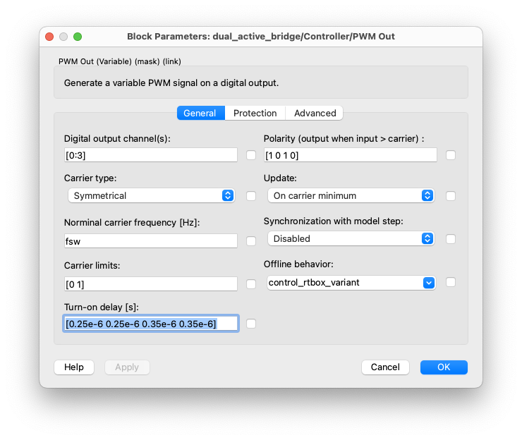
You can have separate dead time values for the PS and SS signals, either by vectorizing the dead time value (“Turn-on delay”) appropriately in the PWM Out block, or adding the delay in line with the switching signals using the Turn-on Delay block.
if i apply turn in delay box it will apply for both ps and ss i need to control individually the both side
Did you try vectorizing the “Turn-on Delay” parameter in the PWM Out (Variable) block? See below:
but its help like different step turn on delay it will apply for both side I’m trying to generate different turn on delay for PS and SS to achieve better efficiency
phase shift modulation.plecs (42.5 KB)
I’m using this model for my phase shift modulation and the PWM Out I’m using the same that provided here. as a result I’m facing some limitation in range I can only apply the range of ‘0.0 to 0.4’ for all the switches
Specifically, the ranges for each switch are:
for S5: -0.6 to 0.4
for S3: -0.4 to 0.6
for S1: 0 to 1
from my understanding this limitation is due to the undermask subsystems. Could you please help me rebuild the model to allow for negative phase shift values for all switches?"
And one more thing i good the expected results on my simulation its not get on the realtime RT BOX
Sorry, unfortunately it’s not clear what you are specifically asking help with. In the modulator model you showed an alternative approach to have a separate turn-on delay of the secondary, so it seems that is working now. What else is not clear? Are you able to provide your full system model?
Three_phase_DAB_working_model_final.plecs (97.9 KB)
By using this approach I can control secondary and primary turn on delay its works fine. and then I face another problem, For my application i want to apply negative phase shift by using the PWM out Variable I can’t able to work with negative phase shift. from my understanding the secondary switches work in different phase shift range
Specifically, the ranges for each switch are:
for S5: -0.6 to 0.4
for S3: -0.4 to 0.6
for S1: 0 to 1
So, I can only apply the range of ‘0.0 to 0.4’ for all the switches
I like to know is it possible to all switches work in a negative range ???. From my understanding this limitation is due to the under mask subsystems. Could you please help me rebuild the model to allow for negative phase shift values for all switches? if its can please let me know how.
Thank You
A negative phase shift can be mapped to an equivalent positive phase shift by adding a positive offset value.