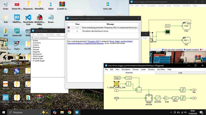
I want to use the PWM generated by the stm32 with the trigger connect in an ADC for “lock”(stay the same value) the ADC’s reading when the PWM signal is low. There’s a way to do that?How the trigger signal affect the ADC’s reading?
The Analog In (Triggered) block will convert when it receives a trigger signal and then hold that value until it receives the next trigger signal. The PWM block can generate a trigger signal for the ADC. The PWM block uses the TIM peripheral and the trigger signal is synchronous with either TIM underflow or TIM overflow events. How these events align with the PWM output depends on the type of carrier (sawtooth / symmetrical) that is used and the polarity of the PWM signal (see the PWM block help for more information).
To trigger the ADC conversion on the falling edge of the PWM output, the carrier type should be set to “Sawtooth” and the polarity should be set to “Active state is logic ‘0’”. See the PLECS model below.
forum_trigger_synchronization.plecs (25.4 KB)
Hello Rafael,
I built my PLECS model using STM32 TSP 1.5.1 and PLECS 4.9.7. In these newer versions, we can access the base sample time value in more places (the base sample time is defined by the discretization step size in the Coder Options menu).
I am attaching a slight variation of the model. I think you should be able to open this model and run it with older versions of PLECS and the STM32 TSP. If you have access to the new versions, I would also recommend updating to STM32 TSP 1.5.1 to benefit from new features and bug fixes!
forum_trigger_synchronization.plecs (31.3 KB)
