Hi,
I have encountered an issue that I would like your help with. I would like to know if it is possible to use separate PWM blocks with two different switching frequencies in TI auto-code generation. I tried this with the F280039C control card, but I wasn’t able to get it to work.
Following is the Project Schematic and the error I am getting.
For the PWM block, I am using 10 kHz, and the PWM1 block 20 kHz. I have set the Tasking mode to Single-Tasking and Step size to 5e-5 (1/20000). Do I need to assign tasks as the multi-level? Can you please give me some guidance for this?
Please find the project file also.
resolver.plecs (40.6 KB)
Hello,
The problem is you have your ADC attached to a control task trigger. This makes it so that the PWM triggering the ADC also triggers the control task. Because this PWM is running at 10e3, the base task is forced to run at 1/10e3 = 1e-4. Removing the control task trigger fixes the problem!
Hope this helps, let us know if you need any further help. I’ve attached a fixed version of the model to this.
resolver.plecs (37.9 KB)
Hi Sulliva
Thank you for the information. I have resolved the previous issue. However, when I run the system in External Mode, I’m noticing noise in the position signal, and my SPWM also gets distorted. Interestingly, when I run both at 10 kHz, the system works well, with clean signals and proper SPWM behavior. Do you have any idea what might be causing this issue at two different frequencies?
Also, I’m trying to acquire a resolver signal and measure speed. For that, I’ve used the following block set in my implementation. However, I’m not getting the correct speed output. I suspect the issue might be related to the initial condition of the integrator block. (Instance that I have used C-script to create a derivative and do the same thing, but with a fixed step, I was unable to do that.)
I’ve attached the PLECS file with this message. Could you please take a look and share your thoughts on the above two issues?
Resolver_V02.plecs (58.0 KB)
Derivative_1.plecs (17.7 KB)
Hello,
To address your first point, I’d be curious what your circuit driving your ADC measurements used to derive your position signal is. Note that as seen in this app note offered by TI (https://www.tij.co.jp/jp/lit/an/spract6a/spract6a.pdf?ts=1750874054282&ref_url=https%253A%252F%252Fwww.google.com%252F), your op-amp (if used) and RC circuit used to drive the input pin (as well as your setting for the ADC acquisition time) can have a notable effect on the accuracy of your readings. What sort of noise are you seeing? Is it any sort of consistent offset, or more seemingly random noise? Also what is the SPWM distortion you are seeing? When I test on my side the functionality appears correct, in what way is the signal not operating as expected? Something you can do on your side to see if this improves the behavior is lower the step size to 2.5e-5, to be able to update the PWM twice per period instead of once. That would be my best intuition on how to resolve.
For the second question, I will defer to my colleague @Bryan_Lieblick who will have better insight on what the potential issue is here. To help clarify, a description of how your speed output is incorrect would be helpful - how is what you’re seeing different than what you’re expecting? And what initial conditions are you assuming? Is your motor standing still or moving? Perhaps I could be misunderstanding so any extra information here would be helpful for debugging.
Sorry I don’t have a ton of answers for you at the moment! As mentioned, general information about the way in which your signals are not as expected will help us a lot to debug with you.
Hi Sachith,
Overall the speed/position decoding approach you’re using is unclear which is something you must develop. How is the excitation signal being generated? Are these the decoded sin/cos values or is the excitation super imposed? How does the derivative block relate to your implementation for resolver speed sensing? If the derivative senses the angle derivative, how will it handle rollovers and reversals?
I can provide the following guidance:
- It would be helpful to have an equivalent offline model of your resolver circuit. That way you can test your algorithm directly. We do not have the hardware to recreate your observations.
- When using the integrator blocks for code generation you should use integrator wrapping and limits where applicable. For example, the integrator you’re using as a clock generator will lose precision as the floating point number grows large. Set it to wrapping.
- Derivative implementations are extremely sensitive to noise. One approach we take in the PID controller block is to set a cutoff frequency for the derivative calculation. You can use a transfer function block to implement a s/(s/kf+1) where kf sets the cutoff frequency. However, this won’t handle rollover which you may require a C-Script for.
Hope that helps!
Hi Bryan,
Thank you for the information. I have developed an offline model using an internally generated position signal, and I’ve attached the simulation file here. However, I’m still unable to obtain the speed measurement.
Speed_Calculation.plecs (23.1 KB)
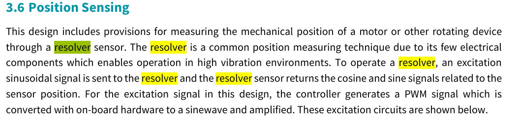
To generate the resolver input, we are using a 10 kHz PWM signal for excitation. A hardware-based filter is used to convert this into a sine wave signal, following the Wolfspeed resolver circuit design.
With this circuit, we are obtaining a smooth position signal.
Now, we want to derive the speed measurement using this position signal. That’s why we are using the above model. However, we are currently unable to obtain a valid speed measurement.
Thanks for the additional details. This helps me better understand your situation.
Overall this is an algorithm design problem not a PLECS problem. The issue is that your integrators can end up with a DC offset at which point your algorithm doesn’t work. You can set the initial condition of the upper integrator to -0.05 in your model and you’ll see the expected speed output.
However this won’t work in real hardware as you don’t know beforehand what the integrator offset will be, or if it will accumulate over time due to measurement error / noise. And how will behave at low speeds?
You likely need a more robust approach than what you’ve implemented, for example a PLL based approach or a zero crossing based approach. The best approach depends on the application and speed profile.