I am using the plecs dual active bridge model. I changed my input voltage, turns ration and the leakage inductance and frequency and ran the simulation. The simulation becomes unstable and tried using various PI controllers but still not working. My input is 20V, output is 360, leakage is 125nH and frequency is 100KHz. Can someone please help me with this ?
I think the issue is with the discrete block in the controller but I am unable to change it.
This is an engineering question and not a “how does this work in PLECS?” question. It sounds like you basically modified the plant model and need to tune the controller accordingly. How did you attempt to do so?
Anyway, the community can’t really help without having your model file(s), so please post those if you are able to.
This is the simulation I am running. I have verifies the Lk and the turns ration works fine using another simulation. (using the same fets as in the Plecs model just for simulation purposes) . I just cant get this to work. Thank you DAB_PI_control_KA_test1.plecs (129.6 KB)
Indeed this appears to be a control tuning exercise. Do you have a closed-loop model running in another tool? If so, what is the control implementation in that version of your model?
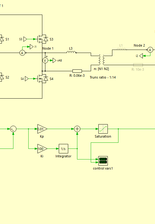
This is what I have in the other model. I replaced the discrete functional block with a PI controller (shown in the figure with same values) and tried the values of my other simulation but its not working.
I thought the issue is with the discrete functional block and it doesn’t let me. Can you please advise ?
Seems like the model is not useable with different parameters.
I’m sorry, but I don’t think you can just change some system-level parameters and use very “nice” Ki/Kp gains and expect the model to run successfully. Did you maintain everything else in the controller besides the transfer function? It’s not obvious from your latest screenshot.
I suspect there are further differences between the two models that you are not accounting for…
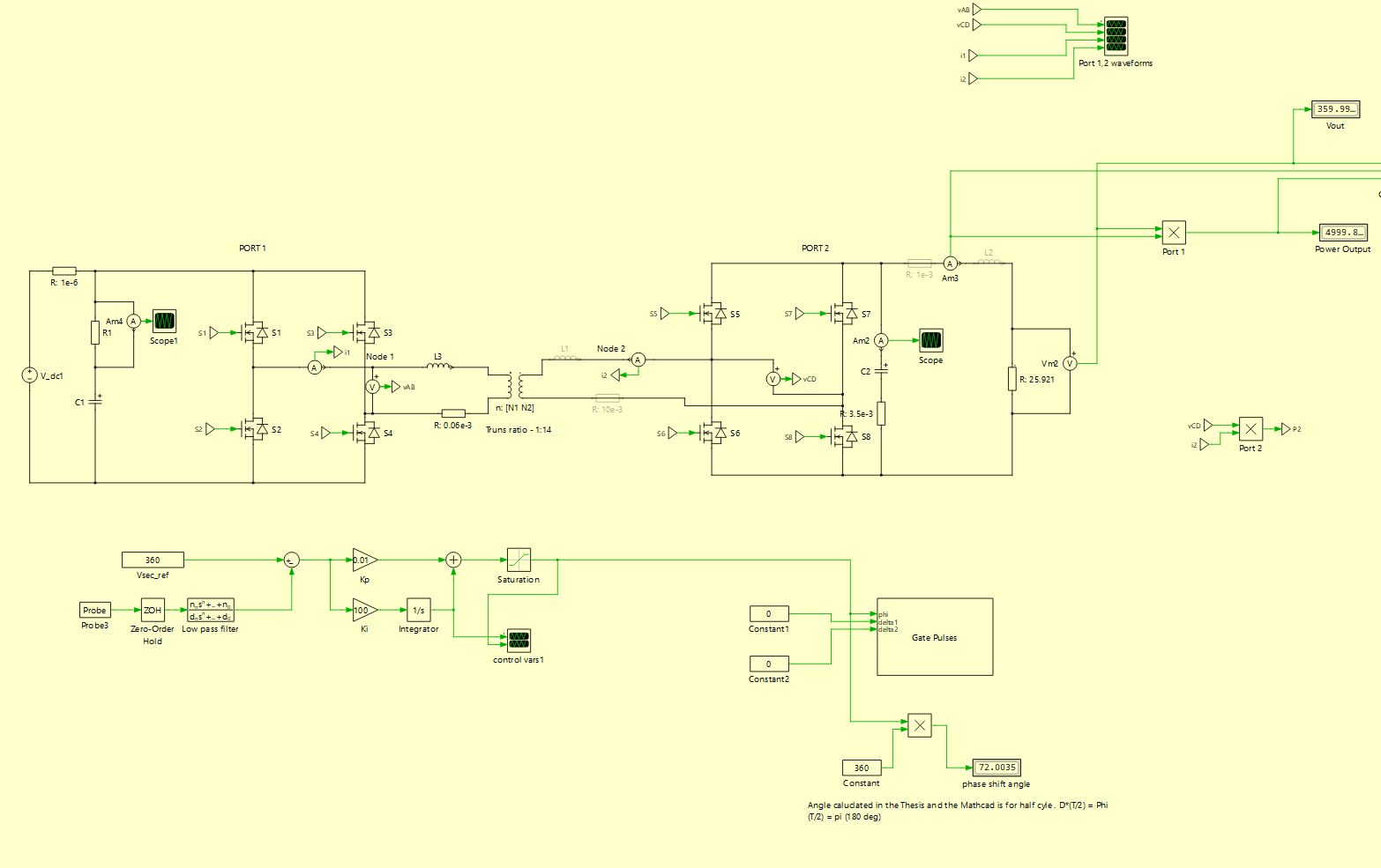
I changed all other parameters in the demo model. Fs-100KHz, Vin-20V Vout-360, Lk-123.4nH, Turns ratio-1:14. Po=5000W. Tried many gains for the PI controller but still not working.
So what would be your solution then ? Can you show me what to be done to run the simulation for above parameters or a different general case ?
Thanks
How are you trying many gains for the PI values, though? Guess and check?
I would first get it working open-loop, have you tried that? Then I would use one of the many PI-tuning techniques to determine a best implementation for closing the loop (assuming that’s necessary for your study).
Hi Kris,
I verified my component sizing is correct from my other simulation [picture attached] it works fine for open loop and closed loop. I want to use the demo model. Demo model does not work for any other parameters.
Does it work for any other parameters ?
After changing the frequency, Vin, Vo, turns ratio, leakage, and the power still it is not working it just crash.
I tried changing the gain values, removed the discrete functional block same.
This is the model from a PhD thesis so I’m curious if Plexim verified if it works for any other parameter. @Bryan_Lieblick Can you please advise ?
Sure, the demo model can be made to work for other parameters, as long as the controller is properly adjusted and you respect the classic laws of the DAB with regards to the power transfer equation and the voltages, phase shift, inductance, etc.
Are you able to post your model here? There’s some obvious differences with regards to passives, but we also can’t see your gate pulse generation scheme.
Out of curiosity, what is it about our DAB demo model that are you are interested in including? Is it just the Wolfspeed FETs? The load step? Something else?
Yes the wolf speed FETs, thermals and the single phase shift. DAB parameters work fine as you can see in this simulation.
Do you have another example of DAB with different parameters ? Because I tried different control strategies with many PI gains but it did not work at all. I guess I will just go with my simulation and include thermal simulations in my version. I hope there were better tutorial examples for plecs… Very powerful software but not many resources out there to use the full functionality of the software.
I looked at your model and I immediately noticed that you were using a fixed step solver with a very small time step. Actually, this is very inefficient and resource intensive. I recommend you use a variable-step solver with the default settings, and just increase the Refine Factor setting, to, e.g. say a value of 5. In the attached version, the model runs much faster and with less simulation steps (data) required.
Further, I copied over the single-phase shift blocks from the other model and provided a fixed (open-loop) phase shift set point initially. This modulation scheme seems to require a much higher phase shift than in your model as you can see. Based on this I think you can get the closed-loop circuit working.
From a quick look it looks like your PI controller output saturation is severely limiting the phase shift and the upper limit may need to be increased a bit or removed all together to regulate the output voltage. I was able to quickly tweak the P and I gain values to get something reasonable, but I will leave that step to you to do in a more methodical way.
Tutorial examples are obviously useful to show what’s possible, but unfortunately customizing them requires true engineering and design work, and we don’t offer those resources as there is already an immense amount of literature available in textbooks and online materials.
Thanks for your simulation!
The reason the saturation is at 90/360 (0.25) is because maximum power transfer is at 90deg, and if it goes beyond that it decrease the power output. That was my understanding.
Thank you Kris I appreciate your help.
What is the reason for the offset block [U-0.5] ?
When I remove the -0.5 offset the phase shift becomes 0.4, which I have in my original simulation I shared here. And your simulation regulates fine without the -0.5 offset at 0.4 phase shift.
OK got it, that is more clear now. We are basically doing the same thing in our model by limiting the phase shift range to 0.25 with the [U-0.5]*0.5 as the carrier upper limit is 1. Anyway, I’m glad that you got your model working now!