Output Impedance Measurement of a DC/DC Converter
The output impedance of a DC/DC converter can be measured by injecting a small current perturbation at a known frequency across the converter’s output terminals and observing the resulting change in output voltage. By analyzing the voltage response relative to the injected current over a range of frequencies, the converter’s output impedance can be plotted using the available analysis tools.

Figure 1: Measuring the Output Impedance of a Buck Converter
The figure above shows the PLECS demo model “Buck Converter with Analysis Tools”, illustrating how the output impedance measurement is performed.
Note: The perturbation signal alone cannot be used to calculate the output impedance, as the converter output current also includes the effect of the output resistor.
To use a different reference signal in PLECS Standalone:
- Double-click the Small Signal Response block.
- Enable Show reference input.
- Feed the measured converter output current into the reference input port.
Input Impedance Measurement of a DC/DC Converter
Often, the input to a DC/DC converter is modeled as an ideal voltage source. The methodology used to measure output impedance cannot be directly applied to measure the input impedance because the ideal voltage source provides a zero-impedance path for the injected current, which interferes with the measurement.

Figure 2: Incorrect measurement of converter input impedance using a current-source based perturbation
Fig. 2 shows an attempted measurement of the input impedance by applying a current perturbation across the input, in the same way the output impedance was measured. The results of this setup are shown in Fig. 3 below.

Figure 3: Incorrect input impedance results using current-source based perturbation
An alternate way to introduce the disturbance is via a voltage perturbation superimposed on the ideal input voltage source. Fig. 4 below shows a setup that applies a voltage perturbation at the input.
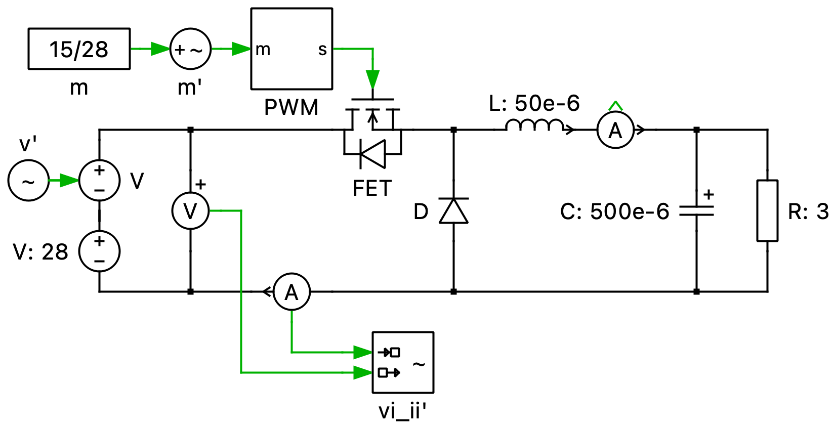
Figure 4: Recommended voltage-source based perturbation to measure input impedance
The results from the setup are shown in Fig. 5 below:

Figure 5: Converter input impedance using a voltage perturbation based approach