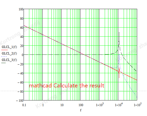
I built an LCL model and wanted to check the resonance point of the LCL, but the simulation still shows the resonance point of the LC circuit. The inductance of L1 is 1000uH, the capacitance of C1 is 10uF, and the inductance of L2 is 10uH. According to the formula, the resonance point should be 16K. What could be the reason?
LCL-bode.plecs (6 KB)
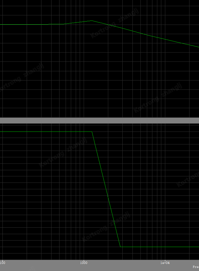
Hello, that’s a great question. The way you have implemented the model on the right side of L2 is an open circuit (voltmeter has infinite resistance in the simulation).
Add a resistor to the model so that there is a path for the current to flow through L2 for it to be effective. With an Open circuit the voltage measurement where you have it now will be equivalent to the voltage measurement across the capacitor and that is why you are seeing the response corresponding to an LC filter instead of an LCL filter. I’ve put a resistor across the voltmeter and the response is now of a system that is not a simple LC filter. Hope that helps!
LCL-bode.plecs (6.5 KB)
1 Like