Recently, I have been working on a CRM-mode totem-pole PFC. The control is mainly realized by calculating the turn-on and turn-off times of the high-frequency main switch based on the mathematical model. Then, the counter value is refreshed when the inductor current zero-crossing is detected.
This △t is actually the main phase period minus twice the phase difference.
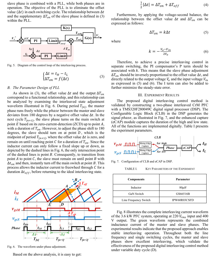
For the closed-loop control, I utilize the captured period of the main phase and the phase difference between the main and slave phases to implement closed-loop regulation. There is a proportional relationship between the output time △t, the phase, and the period, which is expressed as △t = -(Uo - abs(Uin))/2/Uo*(period - 2*phase). However, I have no idea why the phase error correction function cannot be realized after introducing this closed-loop control method, and the waveform even suffers severe distortion. On the contrary, if I abandon this closed-loop control and adopt separate control for the main and slave phases, the waveform will be relatively normal. Could you help me troubleshoot where the problem lies?
The time of the final closed-loop output will be added to the conduction time of the slave phase, dynamically adjusting the phase difference to ultimately achieve the phase staggering function.
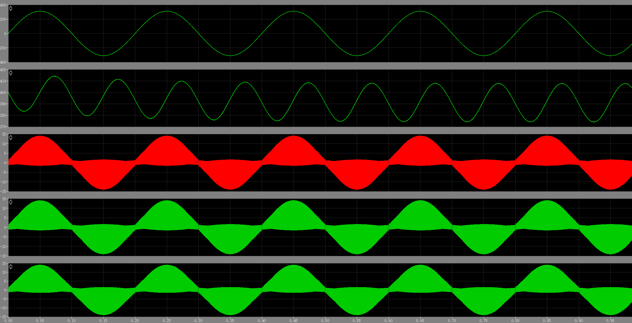
This was tested without closed-loop control, and the performance was decent. The only issue was the lack of phase staggering. However, once I added the closed-loop control, it stopped working properly.
Hi Alps, I’m not very familiar with the control strategy you are working on but would be very interested in learning more. Would you be mind providing a reference to the paper you are basing the controls on?
Like I had recommended in Capture the PWM on-time using C-Script - #2 by Munadir_Ahmed I would avoid C-Scripts. The reason I say this is because the C-Script heavily interacts with the solver and may execute/operate in a way you may not expect. For example if you look at the documentation you’ll notice:
Note It is not safe to make any assumptions about the progression of time between calls to the output function. The output function may be called multiple times during the same major time step, and the time may jump back and forth between function calls during minor time steps. Code that should execute exactly once per major time step should be placed in the update function.
It is for that reason I try my best to avoid using it unless absolutely necessary. Typically that is only to implement discrete controls that I would then want to execute on an microcontroller.
Additionally, your simulation has an algebraic loop and I would recommend avoiding this. Basically you are using Q1-4 to calculate the period and phase and then using these quantities to drive Q1-4 which is forming your algebraic loop. I would consider modeling delays in your controls architecture to break this algebraic loop. Potential options:
filter delays on measurements like electrical quantities
calculation delays
gate driver delays → you could utilize pulse delay blocks to easily model this type of delay
I mainly focus on these four papers. Since there are many formulas involved in real-time calculation, the C-Script module has to be used.
Chen J, Tai W, Xun B, et al. Improved control strategies for totem-pole PFC with true full range ZVS operation[J].
IEEE Transactions on Industrial Electronics, 2022, 70(3): 2419-2430.
Implementation of Close-Loop Control for Interleaved CrM Totem-Pole PFC Converters with GaN Devices
SR Control With Zero Current Detection Delay
Compensation for GaN CRM Totem-Pole
PFC Rectifier
Digital-Based Interleaving Control for GaN-Based MHz CRM Totem-Pole PFC
You can find these papers on Google Scholar.
The logic of real-time time calculation is all derived from the state trajectory.
These are minor issues. We shall make joint progress through mutual learning.
munadir, I have a further question: It is intended to capture half the main phase cycle (namely, half-cycle corresponding to 180 electrical degrees), then configure a delay of this duration for the slave phase counter to realize open-loop phase shifting. This scheme only requires one ZCD to refresh the counter value, yet the implementation of the delay function has perplexed me for quite a long time without a solution.
Hi alps, yes this does sound complicated specially if the PWM is variable frequency and the period is nondeterministic (i.e. PWM turn off is done asynchronously by a comparator). Could you use the period of the previous switching cycle?
I am not sure how you can predict the Tdelay for the current cycle without a more complicated and likely novel control strategy.