Hello. I was learning about the PCM model through this demo and became curious about the slope compensation option.
I saw that the internal logic subtracts a sawtooth wave.
The preliminary explanation says that slope compensation operates when the on-duty of the PCM controller exceeds 0.5, to ensure stable switch operation.
However, when I run the simulation, the operation is not clear to me. Is it a block that activates when the duty cycle exceeds 0.5 to actually reduce the current by the amount ‘A’ that I entered?
buck_converter_with_peak_current_control.plecs (27.8 KB)
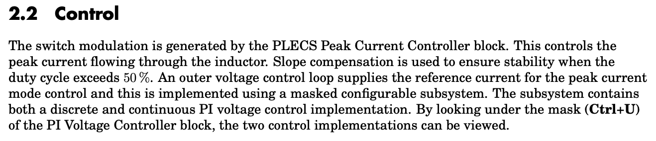
Hello, want to make sure we are on the same page. You are talking about this section?
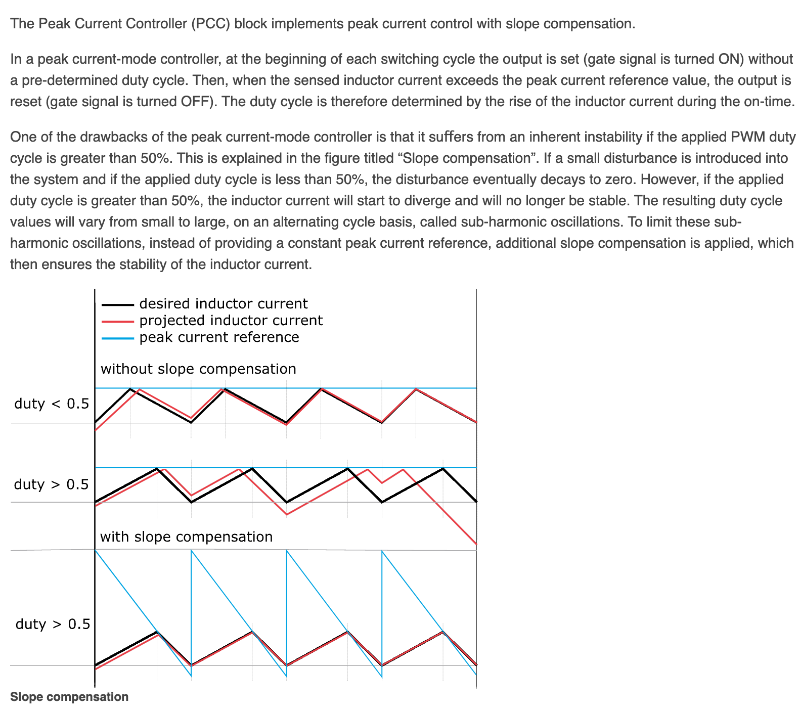
Assuming that is the case the description is less about what the block does differently if duty is >0.5 vs <0.5. It is more about what system design consideration needs to be. Here is a bit more detail on the system design side of things from one of our embedded peak current controller block. It talks about why you need slope compensation when duty is >0.5 vs <0.5 with a nice diagram for illustration:
hope this helps clear out what is happening in the model. If you want to dive into the theory here is a pretty nice article by Ridley works that might be of interest.
thank you for good info
i will take look it